Design
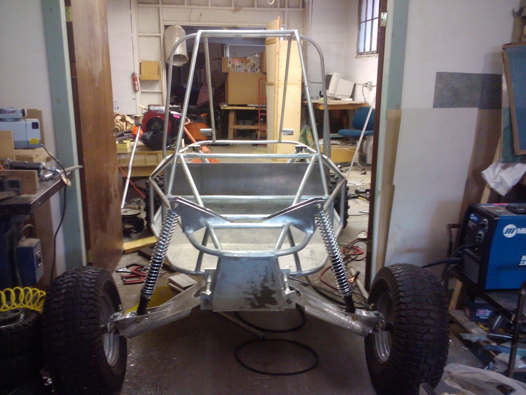
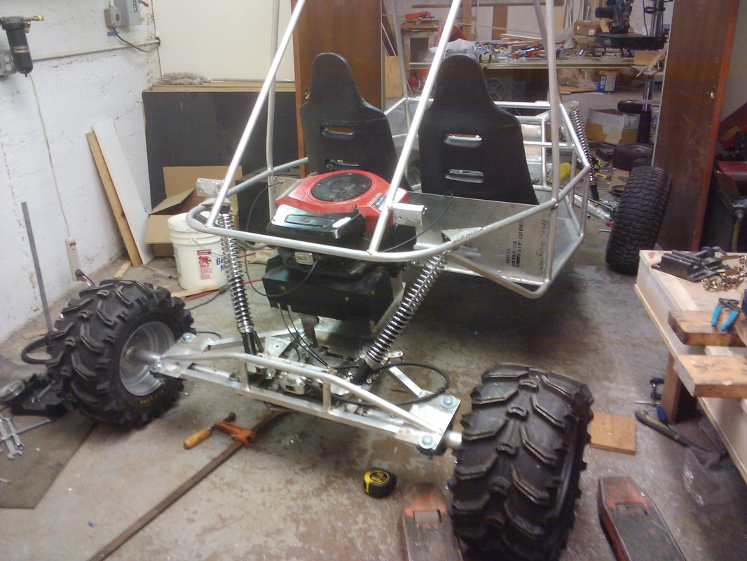
I wanted to build an all-terrain dune buggy with a good stylish look. It would have two seats and big rugged tires, a roll cage, and large shock absorbers. My ultimate goal was to make it street legal. Conventional off-road suspension uses either CV axles with rocker arms and shock absorbers, or straight axles with large leaf springs, or both. I did not have the budget to purchase any of these actual car/dune buggy parts, so I designed my own suspension system that would perform with the same maneuverability as the conventional systems that I could build myself for less money. This was, of course, more labor intensive.
I wanted to build an all-terrain dune buggy with a good stylish look. It would have two seats and big rugged tires, a roll cage, and large shock absorbers. My ultimate goal was to make it street legal. Conventional off-road suspension uses either CV axles with rocker arms and shock absorbers, or straight axles with large leaf springs, or both. I did not have the budget to purchase any of these actual car/dune buggy parts, so I designed my own suspension system that would perform with the same maneuverability as the conventional systems that I could build myself for less money. This was, of course, more labor intensive.


Front Suspension
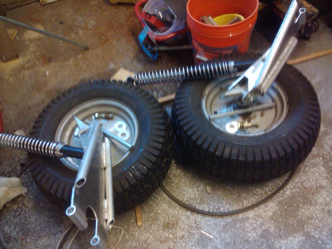
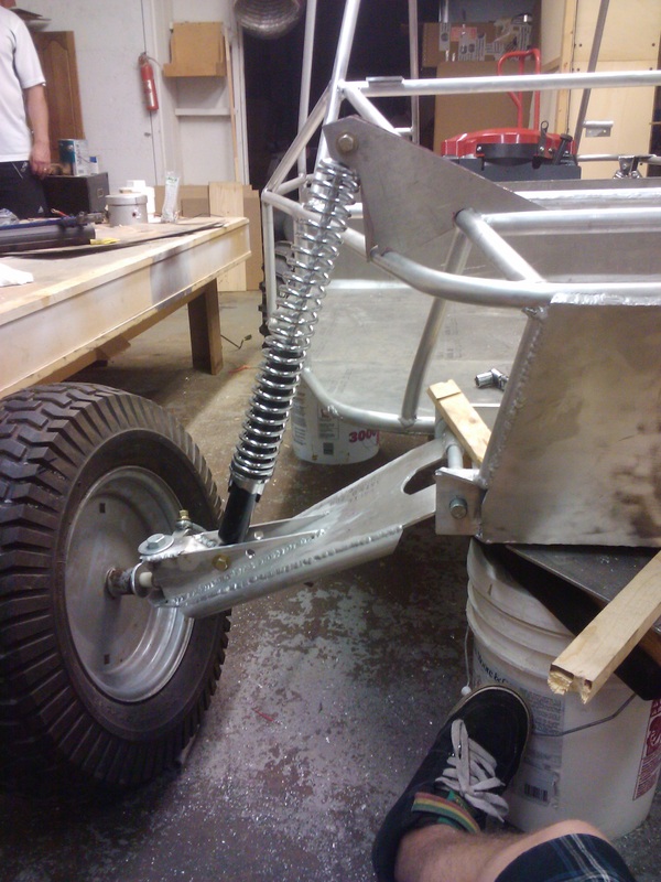
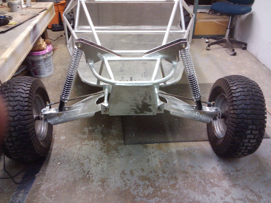
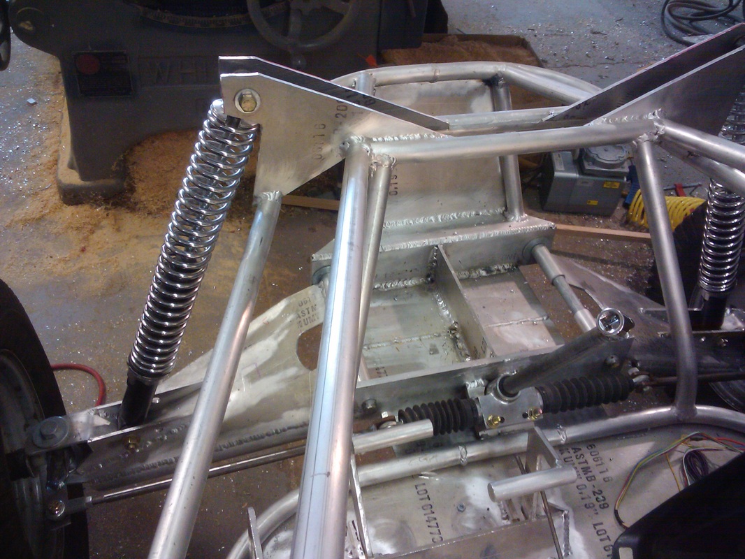
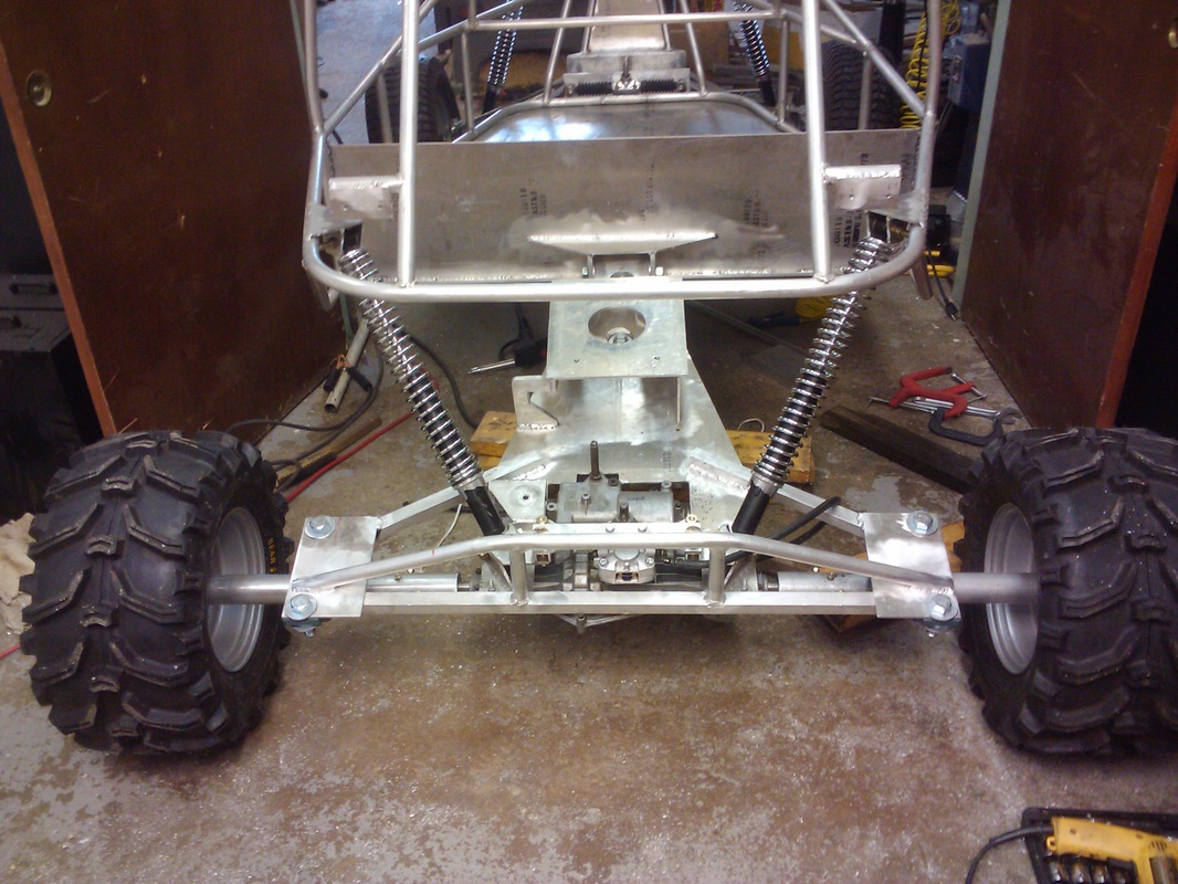
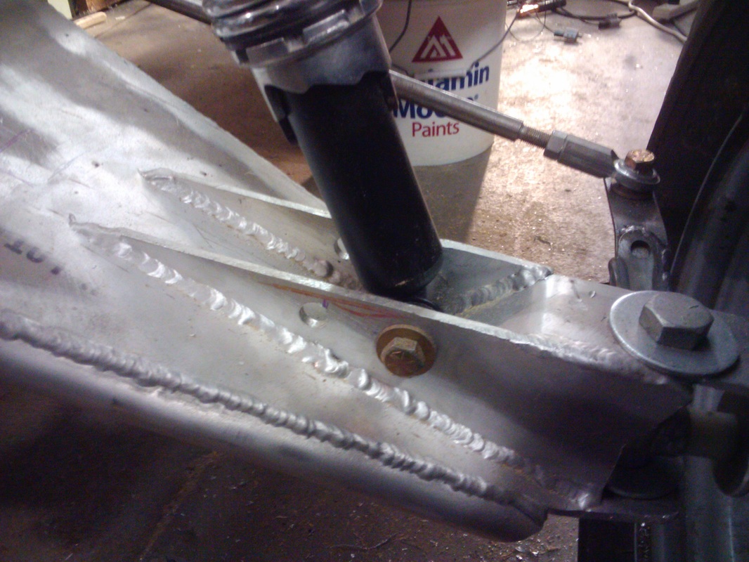
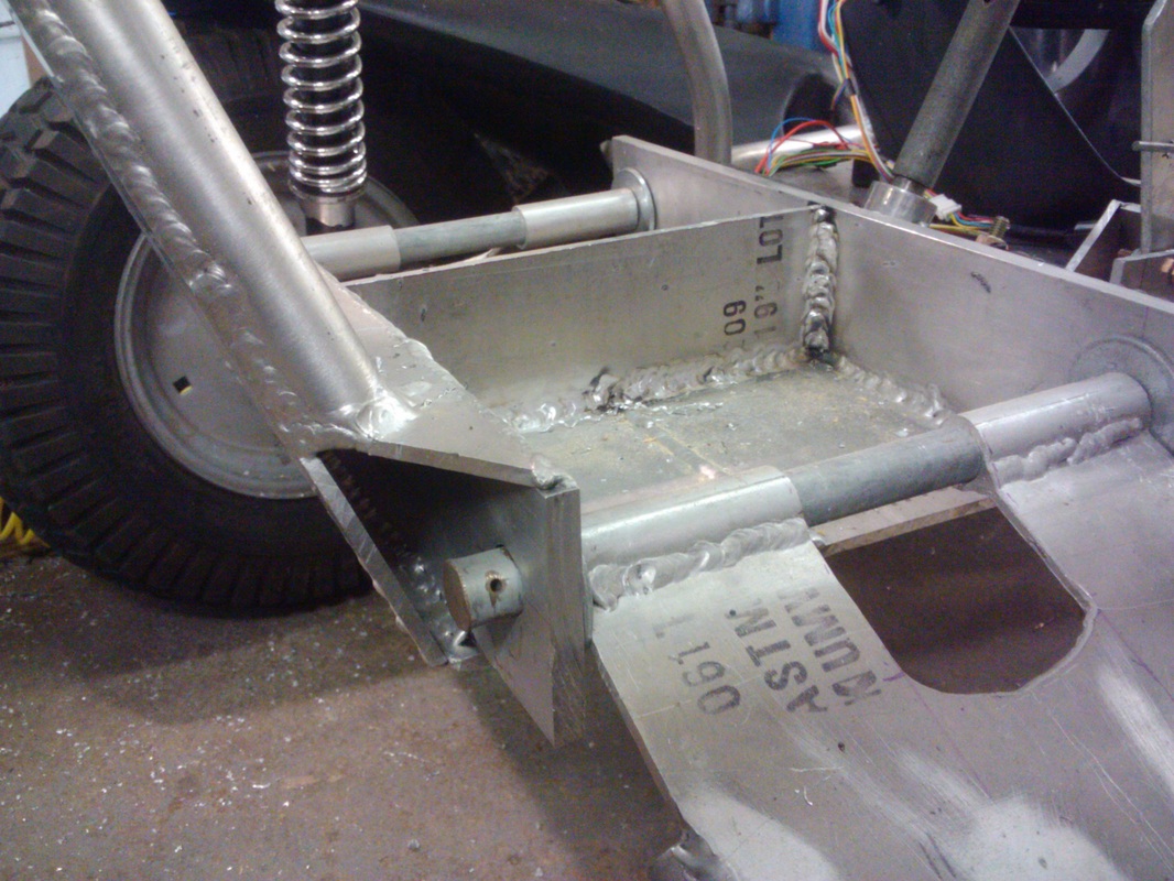
I wanted to use rocker arms for the front suspension so one wheel could go over a rock while the others maintained position. Originally, I wanted to use a parallelogram-style rocker arm configuration because this way the wheel would always stay vertical even if the rocker arm got compressed. However, as I was preparing to build it, I decided it would be simpler to use a single rocker arm and bolt the spindle directly to it. With this configuration the wheel wouldn’t stay vertical when the rocker arm was extended, but it wouldn’t turn off axis enough to cause a problem. I purchased 21-inch coil-over shock absorbers and go-kart spindles from an on-line dune buggy parts supplier. I cut and bent plate aluminum into an A-arm shape. I welded several flanges onto the tip of the A where the spindle would be bolted in. On each leg of the A, I welded on a piece of aluminum tubing. The rocker arms, or A arms, attached to the frame with a large steel rod that went through the tubing on the legs of the A, along with two flanges on either side of the A allowing it to move up and down like a hinge. The bottom eye of the shock absorber is bolted onto one of the flanges to help hold the spindle in place. The top eye is bolted between two flanges extending off either side of the nose of the frame.
I wanted to use rocker arms for the front suspension so one wheel could go over a rock while the others maintained position. Originally, I wanted to use a parallelogram-style rocker arm configuration because this way the wheel would always stay vertical even if the rocker arm got compressed. However, as I was preparing to build it, I decided it would be simpler to use a single rocker arm and bolt the spindle directly to it. With this configuration the wheel wouldn’t stay vertical when the rocker arm was extended, but it wouldn’t turn off axis enough to cause a problem. I purchased 21-inch coil-over shock absorbers and go-kart spindles from an on-line dune buggy parts supplier. I cut and bent plate aluminum into an A-arm shape. I welded several flanges onto the tip of the A where the spindle would be bolted in. On each leg of the A, I welded on a piece of aluminum tubing. The rocker arms, or A arms, attached to the frame with a large steel rod that went through the tubing on the legs of the A, along with two flanges on either side of the A allowing it to move up and down like a hinge. The bottom eye of the shock absorber is bolted onto one of the flanges to help hold the spindle in place. The top eye is bolted between two flanges extending off either side of the nose of the frame.

Rear Suspension
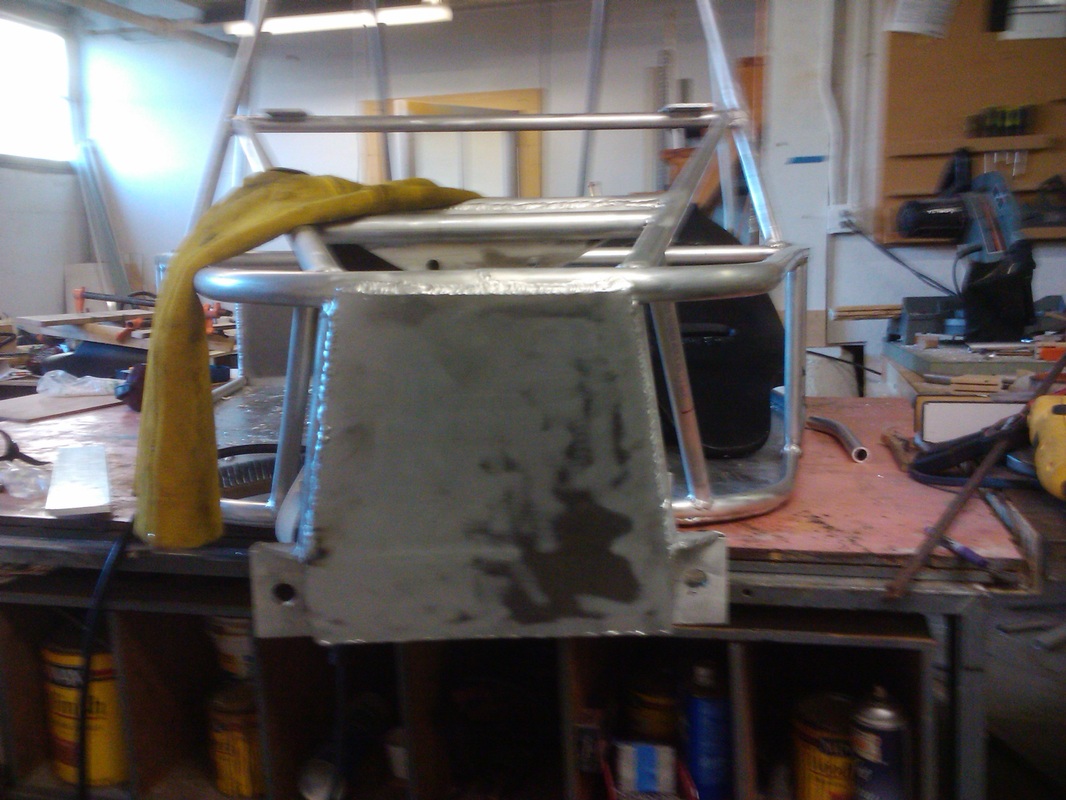
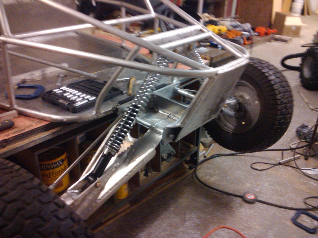
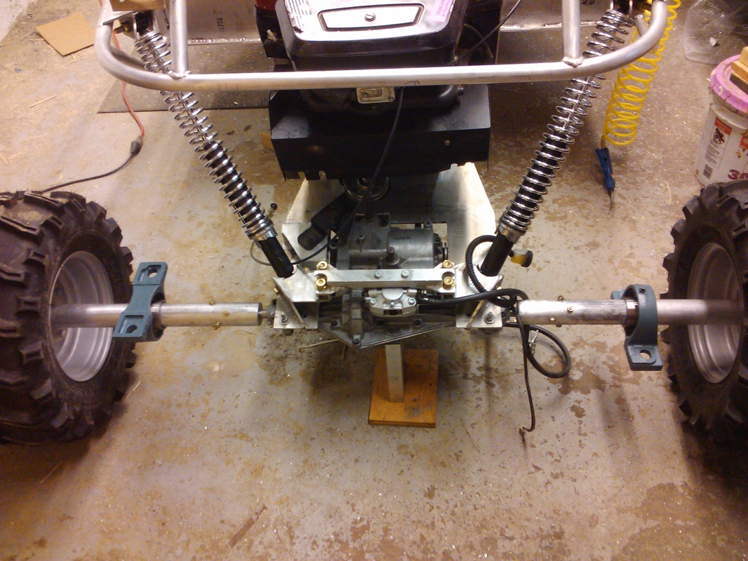
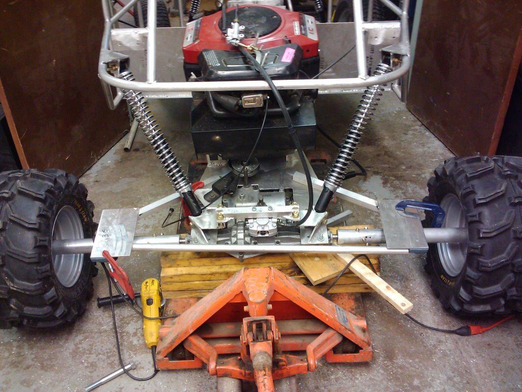
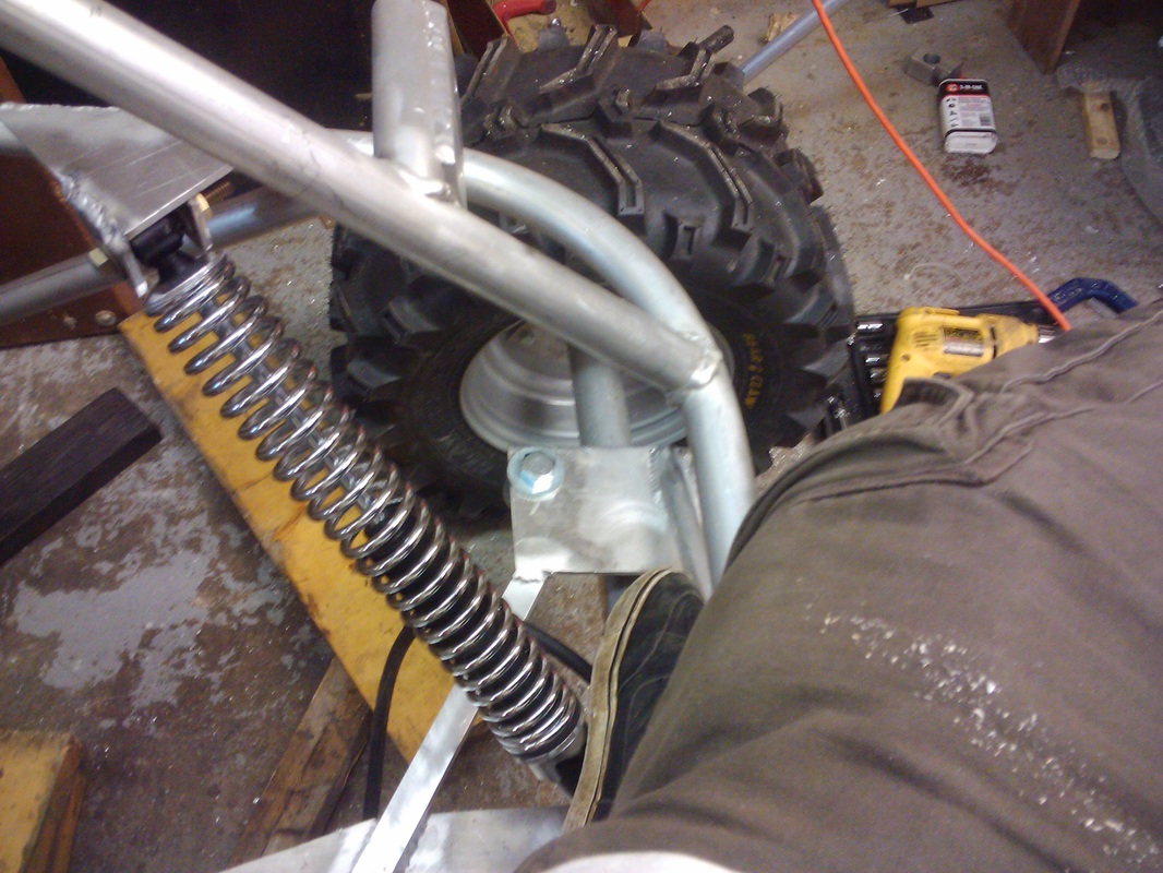
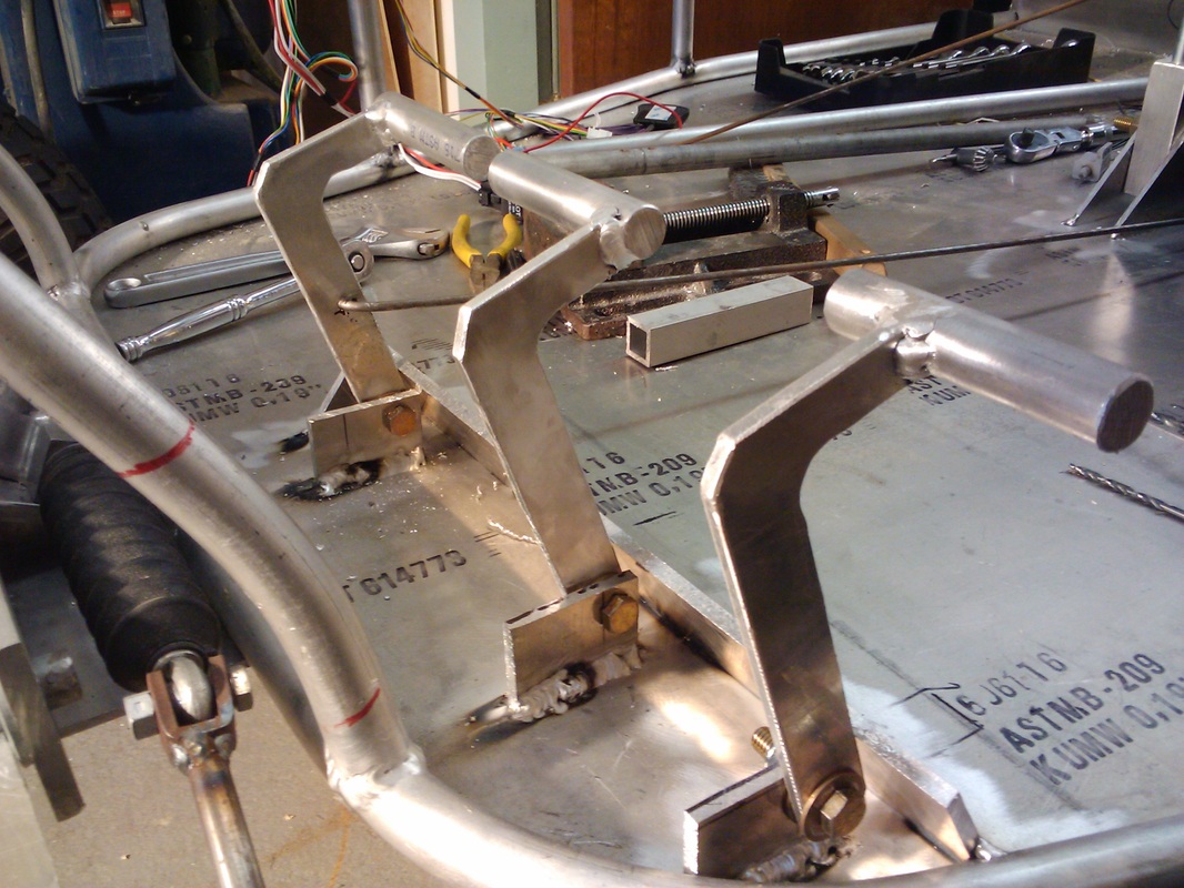
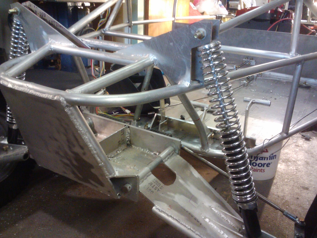
The rear suspension was by far the most difficult element of the go-kart to design and build. It not only has to flex, like any vehicle’s suspension should, but it has to house a differential and drive shaft of some sort. The rear axle of any normal go-kart is easy to build with a straight axle, gearbox and differential. The axle is held with pillow block bearings, which are mounted to the frame, and the differential gearbox is bolted down as well. For go-karts that have suspension, a CV axle and rocker arms are used, or a straight axle with a differential (as seen on many trucks). I only had the parts available to build a go-kart without suspension, but I wanted to be able to crawl over rocks and rough terrain, so I designed my own unique linkage that would allow me to get the suspension I wanted with the parts available. I designed a large triangular plate that my engine and gearbox differential (transaxle) would be mounted on. I made extensions for the axles that extended from either end of the transaxle and bolted them to the ATV tires. To support the axle extensions, I mounted two large pillow-block bearings close to the wheel and welded several reinforcing bars and flanges to connect the bearings with the triangular engine and transaxle mount. The shock absorbers are bolted between two sets of flanges, one above the bearings and the other on the back of the frame.
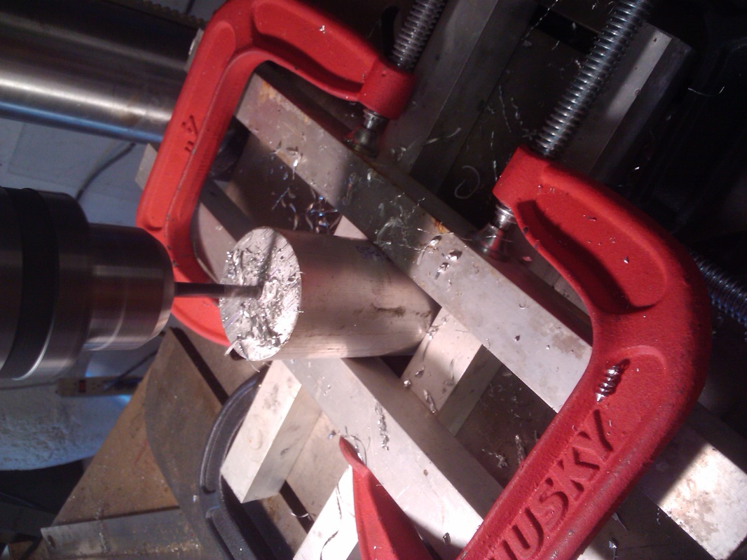
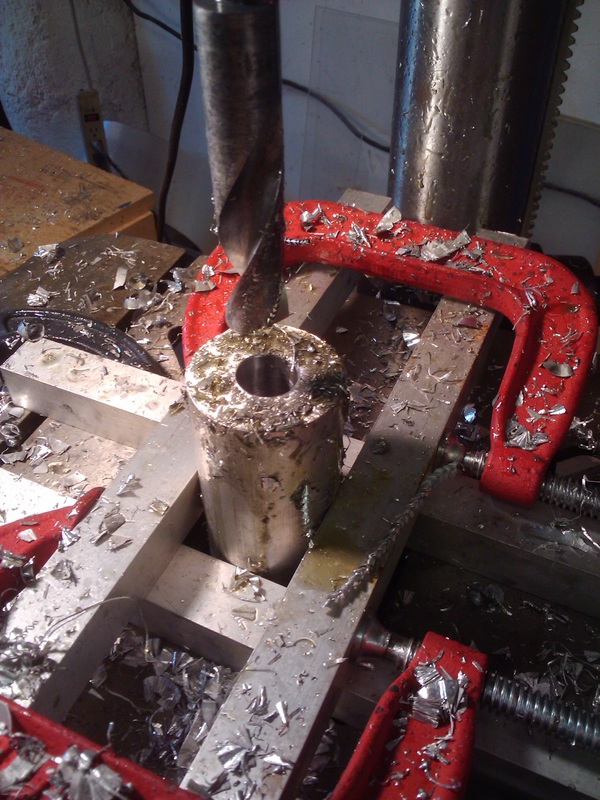
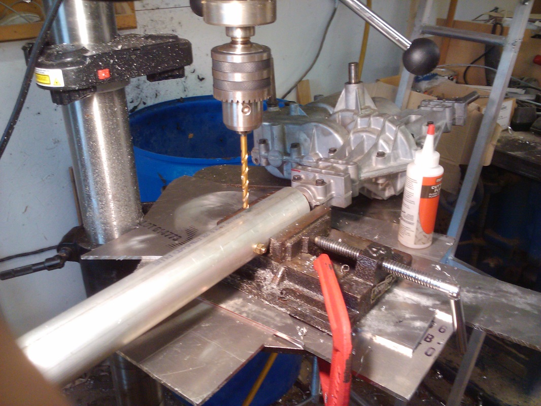
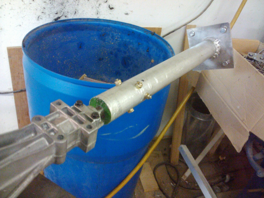
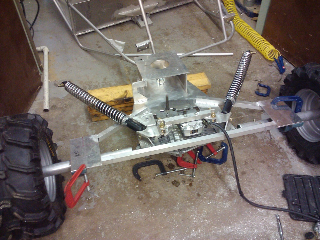
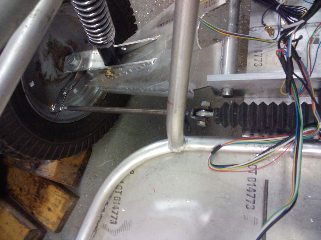
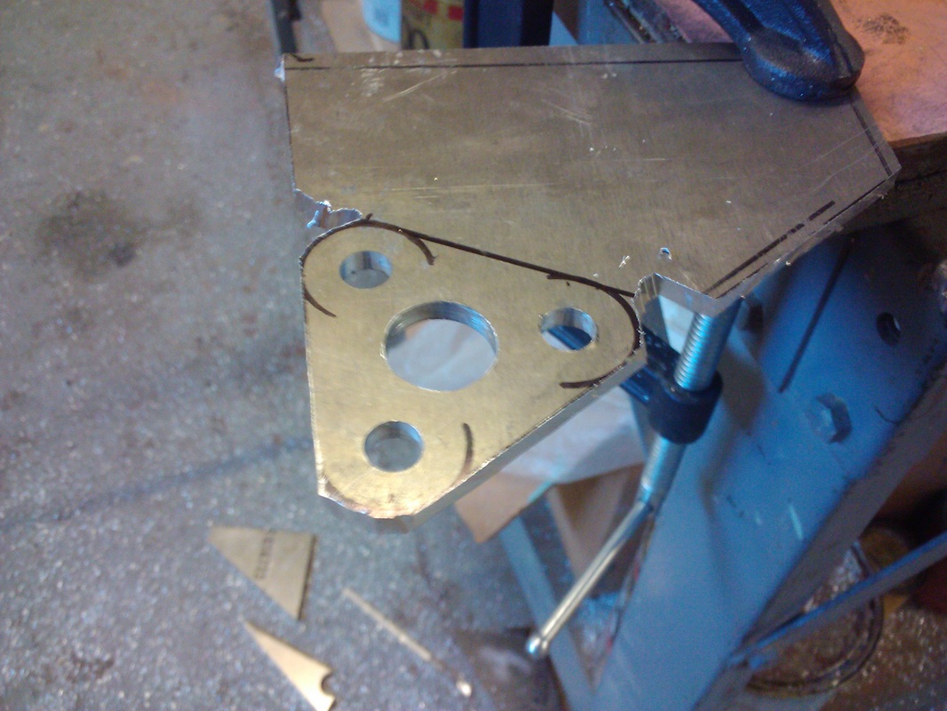
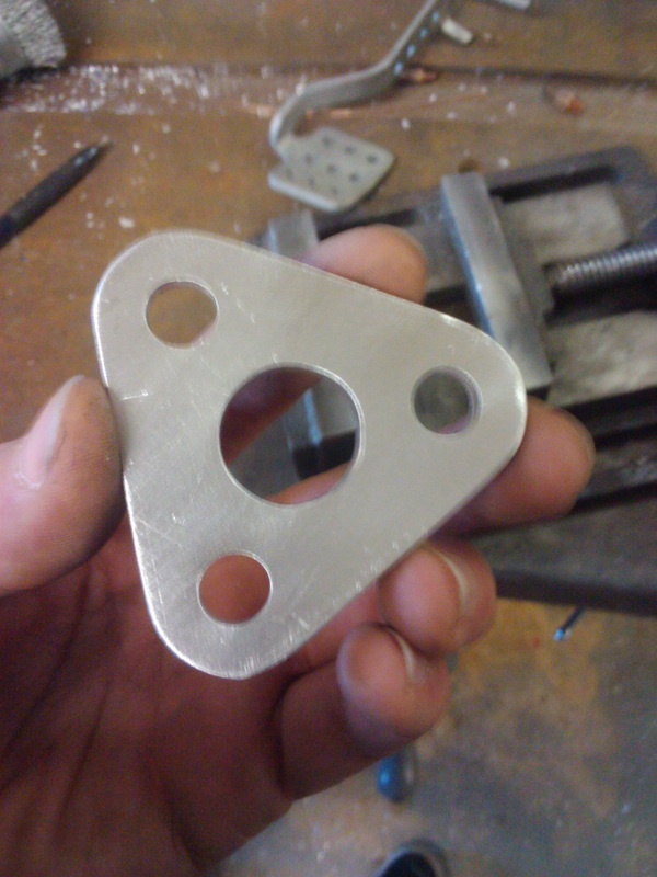
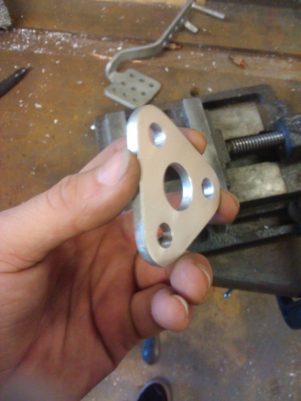
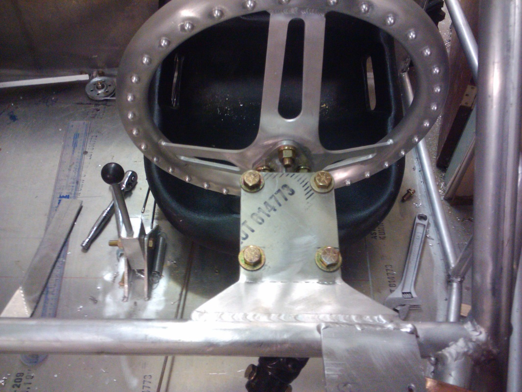
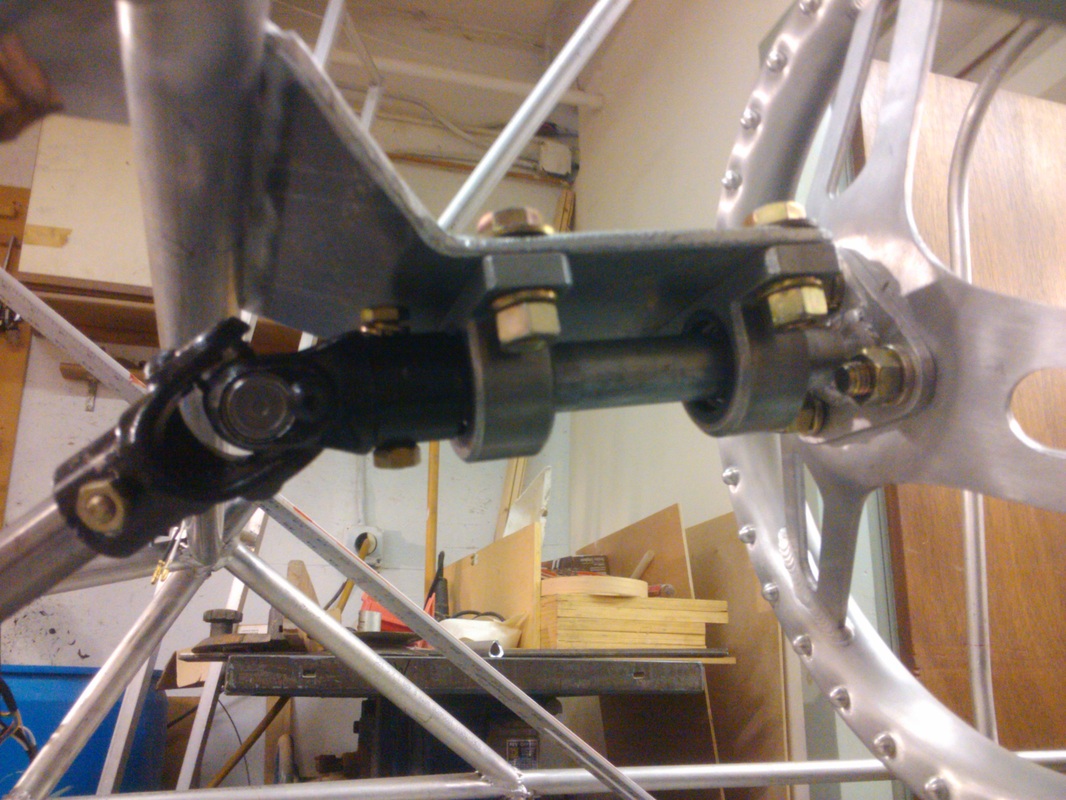
The joint that makes the whole rear suspension work is a sort of a universal joint that I designed and built. One end mounts to the frame of the go-kart, and the other end mounts to the tip of the large triangular flange that holds the engine and transaxle. It allows the back axle to radially move up and down and also to twist, one wheel moving up and the other moving down in either direction.
The rear suspension was by far the most difficult element of the go-kart to design and build. It not only has to flex, like any vehicle’s suspension should, but it has to house a differential and drive shaft of some sort. The rear axle of any normal go-kart is easy to build with a straight axle, gearbox and differential. The axle is held with pillow block bearings, which are mounted to the frame, and the differential gearbox is bolted down as well. For go-karts that have suspension, a CV axle and rocker arms are used, or a straight axle with a differential (as seen on many trucks). I only had the parts available to build a go-kart without suspension, but I wanted to be able to crawl over rocks and rough terrain, so I designed my own unique linkage that would allow me to get the suspension I wanted with the parts available. I designed a large triangular plate that my engine and gearbox differential (transaxle) would be mounted on. I made extensions for the axles that extended from either end of the transaxle and bolted them to the ATV tires. To support the axle extensions, I mounted two large pillow-block bearings close to the wheel and welded several reinforcing bars and flanges to connect the bearings with the triangular engine and transaxle mount. The shock absorbers are bolted between two sets of flanges, one above the bearings and the other on the back of the frame.
The joint that makes the whole rear suspension work is a sort of a universal joint that I designed and built. One end mounts to the frame of the go-kart, and the other end mounts to the tip of the large triangular flange that holds the engine and transaxle. It allows the back axle to radially move up and down and also to twist, one wheel moving up and the other moving down in either direction.
Gear Shift Linkage
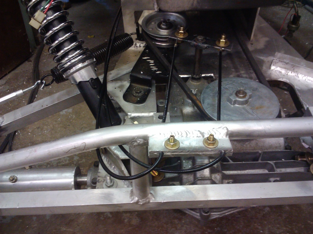
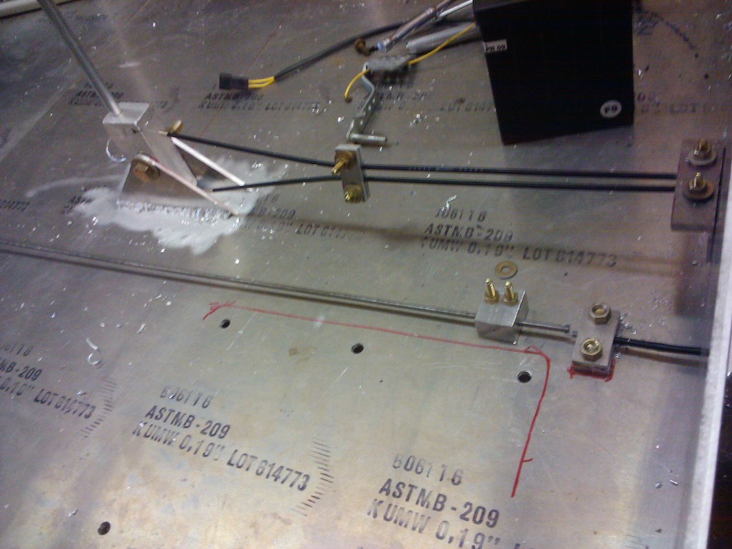
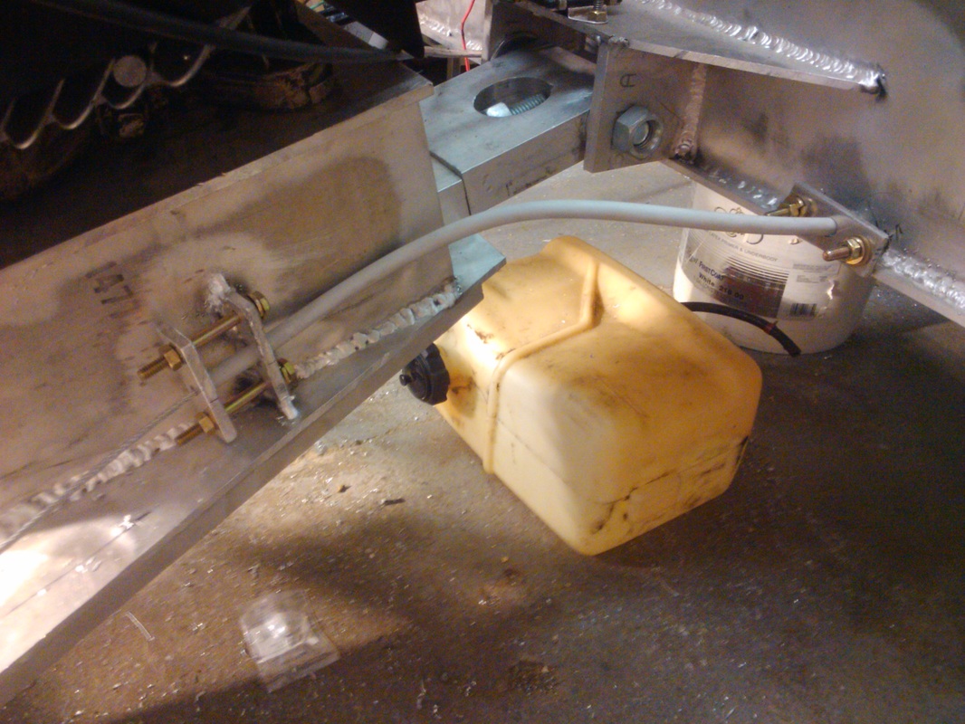
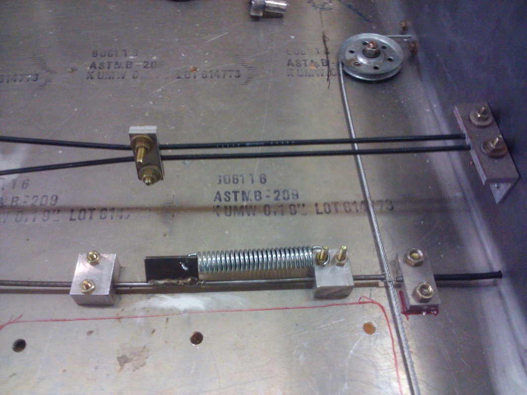
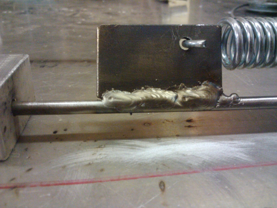
The gear shift linkage was very tricky to design because the cam shaft that gets turned in order to change the gear is located on the gearbox, which is on the back axle. Because of its location on the axle, where it is subject to movement in two dimensions, no conventional rod linkage would be possible. When I was designing this portion of the go-kart, I immediately thought of using hydraulics: two small hydraulic cylinders connected by a flexible hydraulic hose. This, again, was out of my budget. I decided to use flexible coil-over cable lines (such as those found on bicycles). I used two of them and clamped each of their ends side by side, so the cables could move freely inside the sleeve. The sleeve was fixed to the frame, where I would mount my shifting lever, and to the differential where the shifting cam is located. The cable ends were fastened to either end of a flange bolted to the shifting cam. On the shifting lever they were fastened in a similar fashion, one to the upper part of the lever and one to the lower part of the lever. This way, when the lever is pulled backwards, the lower cable is in tension, and it pulls the flange, which turns the cam shaft one direction. If the lever is then pushed forward, the upper cable will be in tension, pulling the flange the opposite direction and shifting back to the previous gear.
The gear shift linkage was very tricky to design because the cam shaft that gets turned in order to change the gear is located on the gearbox, which is on the back axle. Because of its location on the axle, where it is subject to movement in two dimensions, no conventional rod linkage would be possible. When I was designing this portion of the go-kart, I immediately thought of using hydraulics: two small hydraulic cylinders connected by a flexible hydraulic hose. This, again, was out of my budget. I decided to use flexible coil-over cable lines (such as those found on bicycles). I used two of them and clamped each of their ends side by side, so the cables could move freely inside the sleeve. The sleeve was fixed to the frame, where I would mount my shifting lever, and to the differential where the shifting cam is located. The cable ends were fastened to either end of a flange bolted to the shifting cam. On the shifting lever they were fastened in a similar fashion, one to the upper part of the lever and one to the lower part of the lever. This way, when the lever is pulled backwards, the lower cable is in tension, and it pulls the flange, which turns the cam shaft one direction. If the lever is then pushed forward, the upper cable will be in tension, pulling the flange the opposite direction and shifting back to the previous gear.


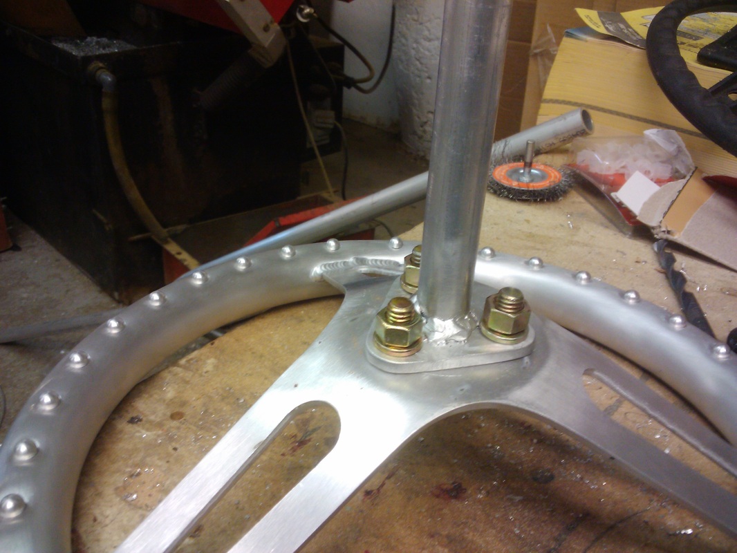
Steering
I used a dune buggy rack and pinion for my steering. I mounted it front and center on the plate that holds flanges for the rocker arms. I positioned it so the eye bolts on either end were perfectly lined up with the rods that held the rocker arms. This way, when the rocker arms were flexed up and down, the tie rod would not be put under any stress that would cause the wheels to turn out of alignment (unless this occurs during the middle of a turn, at which time the rack and pinion is off center, so the eye bolts are not in line with the rods any more).
I used a dune buggy rack and pinion for my steering. I mounted it front and center on the plate that holds flanges for the rocker arms. I positioned it so the eye bolts on either end were perfectly lined up with the rods that held the rocker arms. This way, when the rocker arms were flexed up and down, the tie rod would not be put under any stress that would cause the wheels to turn out of alignment (unless this occurs during the middle of a turn, at which time the rack and pinion is off center, so the eye bolts are not in line with the rods any more).
Clutch
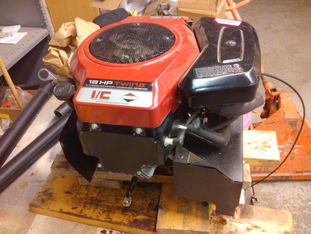
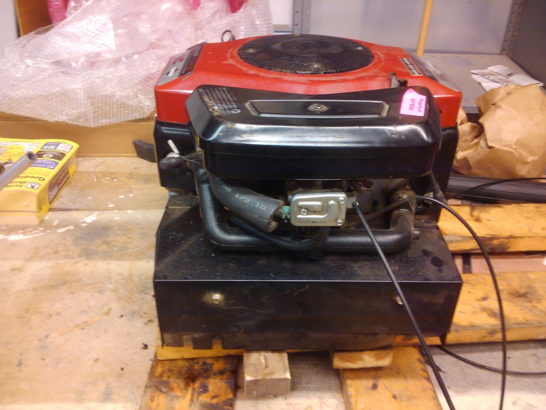
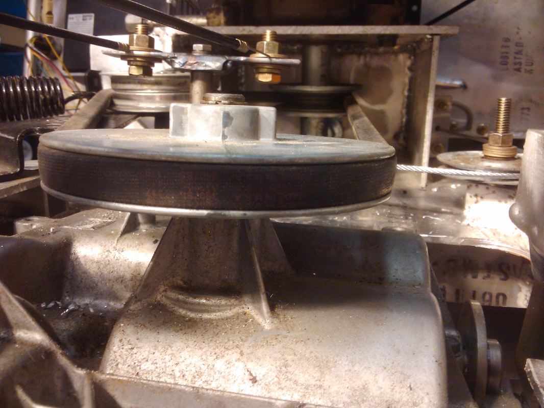
The clutch I designed is a simple belt-tensioning clutch. It was a cheap alternative to a real fluid-plate clutch and functions well enough. It works using three pulleys: two drive pulleys (one on the engine crankshaft and one on the transaxle input shaft) and a tensioning pulley. The tensioning pulley is on a spring-loaded lever, which pulls the belt outward, tightening the belt. In order to engage, the clutch the clutch pedal is pressed down. This pulls a cable, which travels through a series of linkages and in turn pulls the tensioning lever inward, relieving the stress on the belt and allowing it to slip. When the clutch is let out, the pedal is released, and the spring pulls the tensioning pulley tight again.
The clutch I designed is a simple belt-tensioning clutch. It was a cheap alternative to a real fluid-plate clutch and functions well enough. It works using three pulleys: two drive pulleys (one on the engine crankshaft and one on the transaxle input shaft) and a tensioning pulley. The tensioning pulley is on a spring-loaded lever, which pulls the belt outward, tightening the belt. In order to engage, the clutch the clutch pedal is pressed down. This pulls a cable, which travels through a series of linkages and in turn pulls the tensioning lever inward, relieving the stress on the belt and allowing it to slip. When the clutch is let out, the pedal is released, and the spring pulls the tensioning pulley tight again.


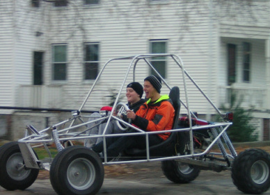
Joy ride!