Infrared Camera System
Eye-R Systems, Inc.
From July 5 through August 11, 2011, I worked as a paid intern for an M.I.T start-up company called Eye-R Systems, Inc. Eye-R Systems has developed a mobile infrared-camera tracking system to measure heat loss in buildings and homes. I worked on the advanced prototype, where I helped design and fabricate the mounting system and helped install it on the platform, a new Ford Explorer, to be driven to Texas for data collection trials.
The Design Challenge
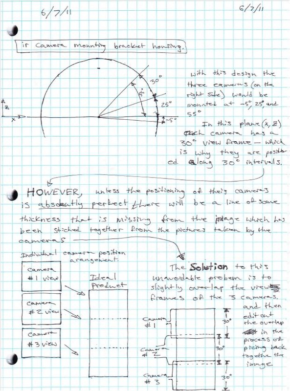
Our task was to design an infrared-camera system that could be mounted on top of a car to log data as the car drove forward. The idea was to scan the landscape on either side of the car and generate a Google street-view type of image of the landscape. Of course, ours would be an infrared scan, which would show where thermal energy leaks are in houses and buildings based on the gradation of the infrared image. Each of the infrared (IR) cameras that we were tasked to configure and mount has a frame of view of 30 X 40 degrees, so it would not be possible to capture the full image of houses and buildings with one unit. Therefore, our camera system mount would have to hold multiple cameras. Multiple cameras means there must be a way to perform minor camera adjustment in order to properly match up the frames of view to capture the whole house or building with no gaps and minimal overlap.
Prototype Design
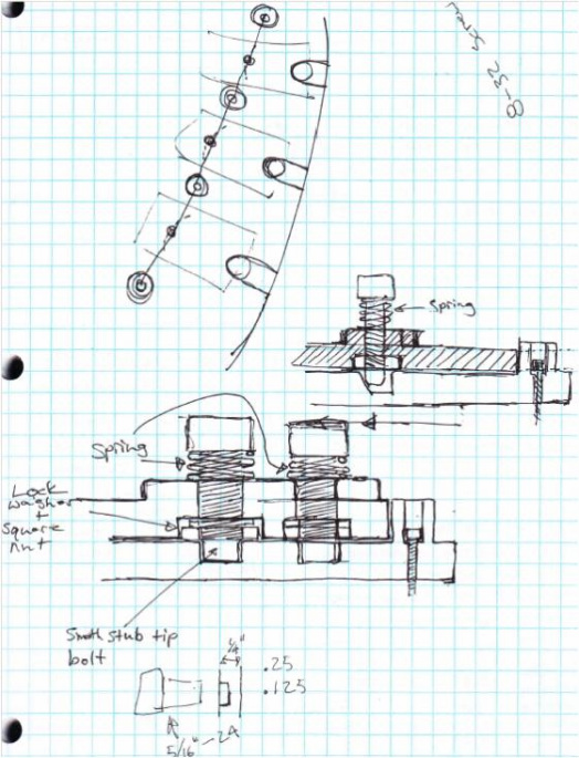
Right off the bat I decided that the best configuration for the IR cameras would be to mount them on two arcs, each with three cameras on it facing the two sides of the road. I reasoned that mounting them on a radial arc would minimize distortion when the full image was pieced back together by the software team. This concept is not my own – I actually borrowed it from nature, specifically the compound eye of a fly. Compound eyes are made up of hundreds of tiny lenses each of which sees a small portion of the surrounding scene. The lenses are positioned on a curved surface so that their focal distances are all the same relative to the center of the spherical surface they are mounted on. The fly’s brain pieces the many images from all the different lenses together to get a very large view of its surroundings. I configured the cameras to function in a similar fashion.
Eye-R Systems, Inc.
From July 5 through August 11, 2011, I worked as a paid intern for an M.I.T start-up company called Eye-R Systems, Inc. Eye-R Systems has developed a mobile infrared-camera tracking system to measure heat loss in buildings and homes. I worked on the advanced prototype, where I helped design and fabricate the mounting system and helped install it on the platform, a new Ford Explorer, to be driven to Texas for data collection trials.
The Design Challenge
Our task was to design an infrared-camera system that could be mounted on top of a car to log data as the car drove forward. The idea was to scan the landscape on either side of the car and generate a Google street-view type of image of the landscape. Of course, ours would be an infrared scan, which would show where thermal energy leaks are in houses and buildings based on the gradation of the infrared image. Each of the infrared (IR) cameras that we were tasked to configure and mount has a frame of view of 30 X 40 degrees, so it would not be possible to capture the full image of houses and buildings with one unit. Therefore, our camera system mount would have to hold multiple cameras. Multiple cameras means there must be a way to perform minor camera adjustment in order to properly match up the frames of view to capture the whole house or building with no gaps and minimal overlap.
Prototype Design
Right off the bat I decided that the best configuration for the IR cameras would be to mount them on two arcs, each with three cameras on it facing the two sides of the road. I reasoned that mounting them on a radial arc would minimize distortion when the full image was pieced back together by the software team. This concept is not my own – I actually borrowed it from nature, specifically the compound eye of a fly. Compound eyes are made up of hundreds of tiny lenses each of which sees a small portion of the surrounding scene. The lenses are positioned on a curved surface so that their focal distances are all the same relative to the center of the spherical surface they are mounted on. The fly’s brain pieces the many images from all the different lenses together to get a very large view of its surroundings. I configured the cameras to function in a similar fashion.
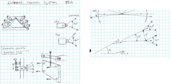
The next challenge was to allow the cameras to be adjustable if for some reason the calculated angles of positioning did not line up. My first idea was to design a cradle for the camera and use two screws, one on either side to fasten it between two plates. This would allow the camera cradle and camera to pivot at the point of the screw. To keep it from moving and allow for minute adjustment, a screw in the back of the cradle could be turned. If it were screwed tighter (clockwise), then the camera would shift to look downward.
This design variation I decided would be a pain to build and would not function as well as an alternative re-design I came up with shortly afterward. I reasoned that the third screw that allows for the adjustment could be mounted in a position perpendicular to the one it had previously been in and just clamp the camera cradle in place.
This design variation I decided would be a pain to build and would not function as well as an alternative re-design I came up with shortly afterward. I reasoned that the third screw that allows for the adjustment could be mounted in a position perpendicular to the one it had previously been in and just clamp the camera cradle in place.
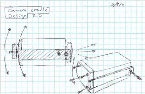
I made several revisions to this design to make it more effective, quick, and easy to make adjustments. The first of was moving the screw that clamps the camera cradle in place to the sides of the camera to make it a less complicated component. Moving it to the side allows it to use a hole drilled in the plates that sandwiches the camera for its mounting versus an additional braced bracket. The second revision was to replace the two screws that the camera pivots off with two rod stubs that would slide into slots. The slot and rod stub would make it so that now the camera cradle needed only two screws to be removed or loosened to allow the camera cradle to be adjusted or removed.
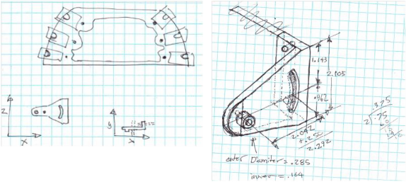
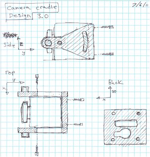
After I designed the cradle on paper, I designed a CAD version in Shark FX. I sent it to a company to request a quote for it to be machined, but it was too expensive for budget. (Unfortunately for the operator/ driver of the camera system, the alternative design that was created after this quote was received was far inferior in its form, function, and ease of adjustment—but that is what happens when a component is designed to cost and not use.)
Re-Design
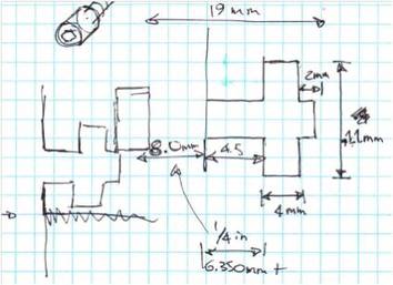
The re-design of the camera mounting system eliminated the use of a camera cradle. Instead, it used four slotted pieces cut from a plate that clamp the camera on the top and bottom of each side. These clamps are then screwed into a slotted track on the two plates that sandwich the cameras. This method of construction is simpler because it eliminates the need for complicated machining. Instead, everything can now be cut out of ¼-inch aluminum plate in less machine time on a water jet CNC machine versus a vertical CNC milling machine and also with less material use.
Mount to Vehicle
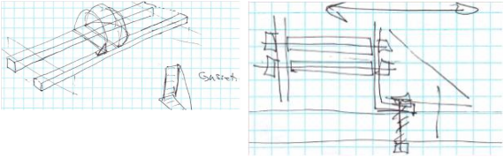
With the IR cameras mounted between their plates, the next step was to mount them to the roof of the vehicle. They would also need to be braced, so they would not blow away when the car is driven fast. The bracing technique we used was gusseting with t-slots. The t was the same dimension as a nut screwed part way onto a bolt, so that the nut and bolt could be slid into the t-slot and tightened, pulling the gusset into the plate and forming the brace.
Re-Design
The re-design of the camera mounting system eliminated the use of a camera cradle. Instead, it used four slotted pieces cut from a plate that clamp the camera on the top and bottom of each side. These clamps are then screwed into a slotted track on the two plates that sandwich the cameras. This method of construction is simpler because it eliminates the need for complicated machining. Instead, everything can now be cut out of ¼-inch aluminum plate in less machine time on a water jet CNC machine versus a vertical CNC milling machine and also with less material use.
Mount to Vehicle
With the IR cameras mounted between their plates, the next step was to mount them to the roof of the vehicle. They would also need to be braced, so they would not blow away when the car is driven fast. The bracing technique we used was gusseting with t-slots. The t was the same dimension as a nut screwed part way onto a bolt, so that the nut and bolt could be slid into the t-slot and tightened, pulling the gusset into the plate and forming the brace.
That took care of bracing in the zy plane, but in order to take care of the bracing in the xy plane, we made a smaller gusset also with t-slots to brace the larger gusset and plate. The four large gussets were slotted on the bottom, so they could be bolted to two pieces of aluminum square tubing with pre-drilled holes. This completed our platform for the infrared cameras.
We were still debating about the best method for mounting the camera assembly to the vehicle. I had originally wanted to use four industrial suction cups, one on each corner of the mount, so that it could be mounted on any car roof regardless of make or model. However, suction cups were too expensive and could potentially be unreliable in extreme weather conditions. We had also debated using a Thule snowboard rack to clamp the camera mount as if it were on a snowboard. This would have been difficult because the size of the square tubing was much larger than the thickness of a snowboard. I then suggested the standard Thule rack, drilling and bolting the camera mount directly to it. This way the whole camera assembly could be removed along with the racks by unclamping the Thule racks themselves, which is very easy.
Twist in Design
In addition to infrared cameras, we now also had to mount eight near-infrared cameras that could work in the daytime. These cameras would record purely structural information about the buildings and houses. They could record street signs and names, housing color – anything that would not show up on an infrared camera. These could work in both daytime and nighttime. The eight near-infrared cameras would be mounted in a way that they would record 3D views of the building versus just a face-on view. The 3D view would be used by the software team to reconstruct a 3D infrared model of the building or house. We decided to mount the near-infrared cameras in such a fashion that two cameras are forward-looking on the left side of the car, two cameras are forward-looking on the right side of the car, two cameras are backward looking on the left side of the car, and two cameras are backward looking on the right side of the car. The reason there are two cameras used instead of three (like the infrared) is because the near-infrared cameras have a much wider frame of view than the infrared, so it takes fewer cameras to capture the same vertical angle. These cameras are mounted on two plates, one on either side, parallel to the infrared camera sandwich. The two plates are held by slots in the large gussets. The cameras have adjustable mounts that are screwed into holes in the plates.
The Nightmare of Wiring
The wiring was by far the most tedious and time-consuming part of the project because there were many more wires to be soldered than nuts and bolts to be tightened. All the cameras came with factory wiring harnesses, but it was decided that the cabling for the cameras was very bulky and ugly and needed to be redone. In each cable, there were several different methods of transferring the same information.
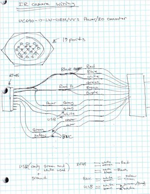
Infrared Camera
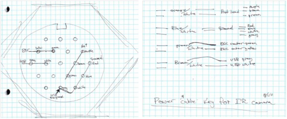
Coming from the infrared camera there was BNC, USB, power and ground connections. USB normally has four signals running through it – two information data, one power, one ground. For our purposes, we needed to use only the two information cables and ground the USB to the common ground. The BNC cable has an information center conductor cable and a ground shield. Then, of course, there is DC power and ground. In total, there are six signals per camera. Our idea was to use RJ-45 cat 6 ethernet cable to run our signals from all of the cameras. RJ-45 has eight wires inside it, which leaves two extra. This is perfect because the wires in the RJ cable are a fairly small gauge, and the original power cables were about double the thickness. We doubled up two wires for power and two for ground. This used all the available wires in the cable and gave adequate conduction for power and ground. Each infrared camera has a special cable connector that screws into the back of it. This connector has 19 ports arranged in a hexagonal grid; however, only 12 of them are actually used. In order to wire up the RJ-45 cable to the camera connector, we had to test with a multi-meter and find out which ports were which and label them accordingly. There were 19 wires, but not 19 colors, so there were duplicates of each wire, and they could not be differentiated without a continuity test with a multi-meter. It took several hours of continuity tests and snipping of the wires that we didn’t need to prevent confusion in order to prep all of the infrared camera connectors for mating with an RJ-45 cable. Then it took about a day of soldering and shrink tubing all of the little tiny wires to the other little tiny wires of the RJ-45 cables and then making them look sleek and professional, which they did. Note: the ugly, bulky camera cables that came with the infrared cameras cost about $500 each. I was able to manufacture a smaller, neater, nicer cable on my own for all six of the cameras in less than two days.
Near Infrared Camera
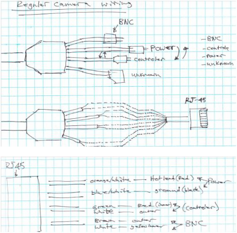
The near infrared camera cable had a BNC, power, controller, and an unknown branch. Again, we wanted to standardize our cabling and make this connect to an RJ-45, so we could use our large 16-port patch panel to connect them all, making it nice and neat. For the near-infrared camera wiring, we needed only the BNC, power, and controller cables. This again resulted in six conductors that needed to be carried through the RJ-45. As before, there were two extra conductors in the RJ-45 cable, so we doubled up the power again.
The near infrared camera cable had a BNC, power, controller, and an unknown branch. Again, we wanted to standardize our cabling and make this connect to an RJ-45, so we could use our large 16-port patch panel to connect them all, making it nice and neat. For the near-infrared camera wiring, we needed only the BNC, power, and controller cables. This again resulted in six conductors that needed to be carried through the RJ-45. As before, there were two extra conductors in the RJ-45 cable, so we doubled up the power again.
Camera Wiring Complete
Now that we had all the camera cables standardized, we mounted a coupler rack patch panel on our camera system. All the leads from the camera would plug into one side of the coupler panel. On the other side, we would connect our 15-ft RJ-45 extension cables that would run across the roof of the car into the sunroof and connect to the master panel located in our hardware box. The master patch panel was almost as much of a pain as the infrared camera cabling. On one side, there are RJ-45 couplers which all of the cables plugged into. On the back side, there are a bunch of prongs which all of our corresponding leads would be crimped and later soldered to. Using our color-coding chart that we previously created when converting the camera cabling to RJ-45, we then broke off the strands of cables to go to the BNC, power, USB and control (for the near-infrared camera). To power the near-infrared cameras, we had a power converter box that regulated the voltage to the correct value for the cameras. We used several RJ-45 cables again with coupler in between to connect all the power leads from the patch panel to the converter box, thus making it easily removable by undoing the couplers. All the BNC cables from the infrared and near-infrared got wound into a strain relief and then were plugged into their corresponding positions on the DVR. The USB leads from the patch panel were soldered to USB cables and plugged into a USB hub. (Later it was found that there was too much information flowing through each USB for the computer to be able to read when they were all coupled at the hub at the same time.)
We found we could safely run two infrared cameras off one infrared camera power supply, so we coupled the infrared camera power leads from the patch panel and used half the number of power supplies and saved space. All of the RJ-45 cables had to be labeled relative to their corresponding camera, so when they were unplugged they could be reconnected correctly. This was easier said than done, since 6’s and 9’s look alike.
Homestretch
The DVR is connected to a computer monitor that shows all the camera displays at once in real time. One of the last steps was to mount the monitor, DVR and hardware box (patch panel, power supplies, USB hub) in the vehicle. The middle row of seats was removed, and they were mounted to the floor in their place.
At this point, the camera system went on several test runs to make sure everything worked properly. Prior to the test drive, two inverters were installed in the vehicle to provide the power needed for the components. The inverters changed the dc power coming from the alternator into ac. Then from the inverters, a UPS (uninterruptable power supply) was connected to ensure that if the car somehow broke, the memory of the DVR would not be lost due to an accidental improper shutdown. However, the inverter was a piece of junk. It changed the dc to an ac signal by approximating a sine wave with many square waves. This normally is all right, and most appliances can’t tell the difference. However, the UPS is too smart and detects the bad sine wave and rejects it, resulting in loss of power to our system. This made it impossible to use the UPS with the inverters. Therefore, we ran the equipment directly off the inverters, and everything worked fine.
Another thing that was discovered on one of the first test drives, this time at night, was that the near-infrared cameras did not have quite enough light to get a crisp image. The image was a bit blurry because there wasn’t enough light for it to focus properly. We addressed this problem by mounting two new near-infrared cameras with illuminators on either side of our camera assembly. Since we were only using these additional cameras for their illuminator function, the only wire we had to hook up was the power. The problem was solved – the reflected light from the illuminator provided sufficient light to boost the thermal gain of the image captured by the infrared camera.
Conclusion
This job gave me the opportunity to put both my design skills and mechanical expertise to productive use to contribute to creating and building a product design. I was also exposed to a complex electronic sensor system and learned basic theory and electrical system considerations. I enjoyed being part of the team, sharing ideas and working together toward the common goal.
Our prototype system image results are shown below.
www.theatlanticcities.com/technology/2011/10/cat-scans-for-cities
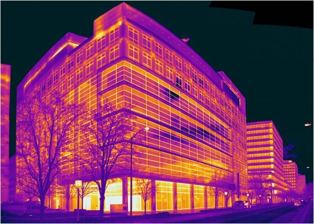
Courtesy of Massachusetts Institute of Technology
Researchers at the MIT Field Intelligence Lab have taken the technology (camera plus sophisticated software) one step further to capture not just the presence of energy, but also the precise windowsills, joists and doorways where it seeps from drafty buildings.
Researchers at the MIT Field Intelligence Lab have taken the technology (camera plus sophisticated software) one step further to capture not just the presence of energy, but also the precise windowsills, joists and doorways where it seeps from drafty buildings.