Design: Side-Mount Engine
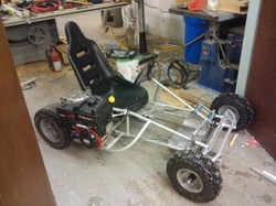
I designed my second go-kart to be a much smaller, simpler street-kart. I had some left over parts from the dune buggy and a small 6.5hp Briggs and Stratton go-kart engine. In designing this go-kart, I took into account function first and then determined its form based off it. I wanted to be able to fit this go-kart in the back of our car, so it could be easily transported. This meant it could only be a certain length and width. My legs are fairly long, so for them to fit with the engine mounted behind the seat, the go-kart would be too long to fit in the back of the car. The solution to this problem was to mount the engine next to the driver's seat, shortening the length by almost a foot and a half. To compensate for the weight of the engine, I mounted the seat a little bit to the left of center. The frame I designed was relatively simple: two parallel tubes with cross members make up the base, and a third tube above and slightly to the left (looking from the back) braces the two base tubes in the third dimension and also supports the extension plate which the engine is mounted on.
I designed my second go-kart to be a much smaller, simpler street-kart. I had some left over parts from the dune buggy and a small 6.5hp Briggs and Stratton go-kart engine. In designing this go-kart, I took into account function first and then determined its form based off it. I wanted to be able to fit this go-kart in the back of our car, so it could be easily transported. This meant it could only be a certain length and width. My legs are fairly long, so for them to fit with the engine mounted behind the seat, the go-kart would be too long to fit in the back of the car. The solution to this problem was to mount the engine next to the driver's seat, shortening the length by almost a foot and a half. To compensate for the weight of the engine, I mounted the seat a little bit to the left of center. The frame I designed was relatively simple: two parallel tubes with cross members make up the base, and a third tube above and slightly to the left (looking from the back) braces the two base tubes in the third dimension and also supports the extension plate which the engine is mounted on.
Steering
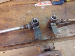
The steering is about as simple as it gets (while still being functional). The spindles are made from a T-pipe fitting welded to an axle rod for the wheel and also to the steering flange. The flange extends perpendicularly from the pipe fitting and axle. The spindles are fixed to the frame by two bolts that pin each spindle in place between the top and bottom flanges of the frame. The spindles are now able to rotate laterally. To keep them aligned, the flanges are each bolted to one end of an L-bracket. (Instead of a rack and pinion, I used a piece of L-bracket.) The spindles and bracket together form a parallelogram which flexes side to side turning the wheels left and right as it does. The steering column is held by two pillow-block bearings mounted to a vertical flange. The end of the column has a flange welded to it. The end of this flange is bolted to a piece of L-bracket, which is bolted to the steering parallelogram configuration. This steering configuration is surprisingly effective and handles well.
The steering is about as simple as it gets (while still being functional). The spindles are made from a T-pipe fitting welded to an axle rod for the wheel and also to the steering flange. The flange extends perpendicularly from the pipe fitting and axle. The spindles are fixed to the frame by two bolts that pin each spindle in place between the top and bottom flanges of the frame. The spindles are now able to rotate laterally. To keep them aligned, the flanges are each bolted to one end of an L-bracket. (Instead of a rack and pinion, I used a piece of L-bracket.) The spindles and bracket together form a parallelogram which flexes side to side turning the wheels left and right as it does. The steering column is held by two pillow-block bearings mounted to a vertical flange. The end of the column has a flange welded to it. The end of this flange is bolted to a piece of L-bracket, which is bolted to the steering parallelogram configuration. This steering configuration is surprisingly effective and handles well.
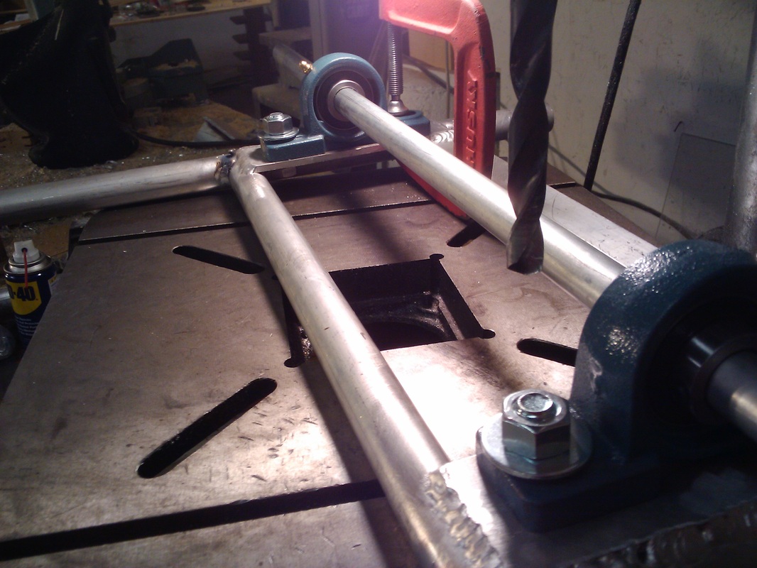
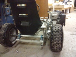
Front end of frame being clamped for welding.


Brakes
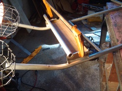
The brake caliper is bolted to a flange that hangs over the disk, and the hydraulic line runs to the cylinder that is mounted between and below the legs of the driver. From the hydraulic cylinder, an extension rod runs up to the lower portion of the brake pedal.
The brake caliper is bolted to a flange that hangs over the disk, and the hydraulic line runs to the cylinder that is mounted between and below the legs of the driver. From the hydraulic cylinder, an extension rod runs up to the lower portion of the brake pedal.
Rear Axle
The rear axle of this go-kart is straight and has no differential or suspension. It makes taking tight turns a little bit difficult, but overall works just fine. Looking from the back, the drive sprocket and disk brake are bolted to two flanges welded onto the axle. The chain runs around the sprocket directly to the centrifugal clutch which slides onto the end of the crankshaft.
The rear axle of this go-kart is straight and has no differential or suspension. It makes taking tight turns a little bit difficult, but overall works just fine. Looking from the back, the drive sprocket and disk brake are bolted to two flanges welded onto the axle. The chain runs around the sprocket directly to the centrifugal clutch which slides onto the end of the crankshaft.